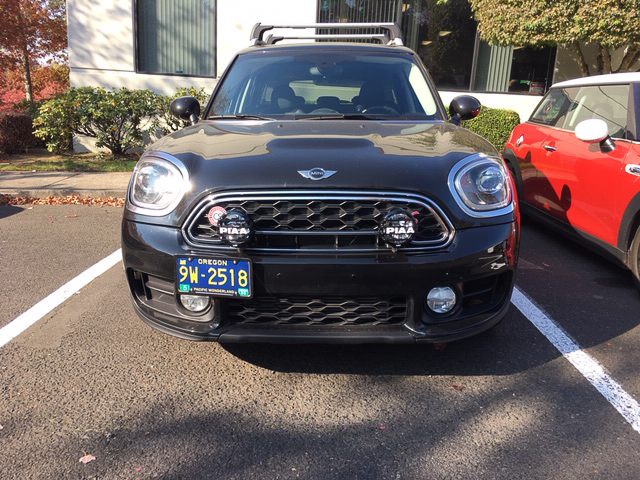
THANK YOU for purchasing the Rally Light Kit for MINI Cooper F60 (2017-2019) from CravenSpeed. This product is made from the highest grade materials, and is guaranteed to be free from defects.
You can buy our CravenSpeed Auxiliary Light Kit for MINI F60 here
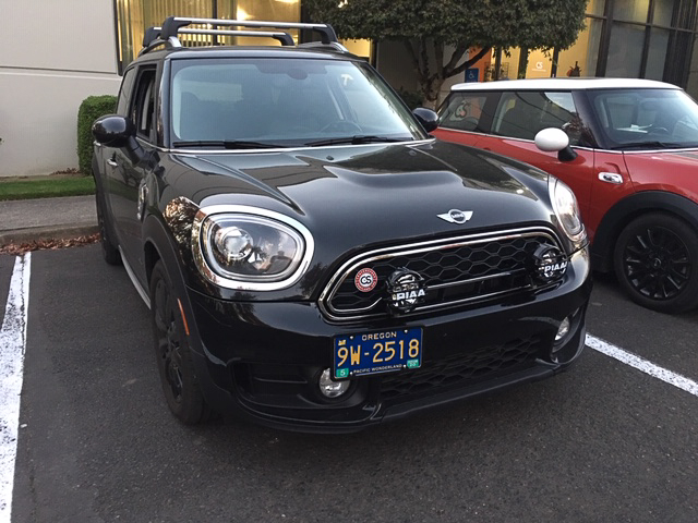
Parts Included:
- 1 x PIAA 5" LP550 High Intensity LED Driving Lamp Kit (two lights)
- 2 x CravenSpeed F60 Aux Light Brackets
- 2 x Threaded “Dog Bone” Clamps
- 8 x 1/4-20 x 1.25" Stainless Steel Socket Head Cap Screws
- 1 x 1/4-20 x 1./2" Stainless Button Head Screw w/Locknut
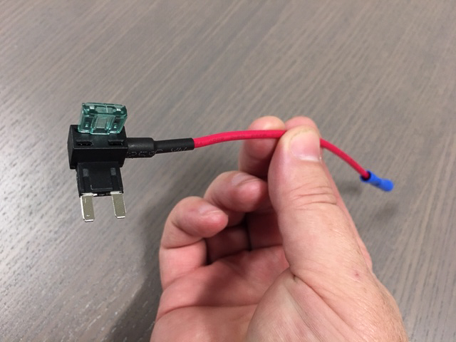
- 1 x Add-a-Circuit Fuse Holder w/1mA Mini Fuse
- 5 x Zipties
Tools Required:
- Ratchet w/ 8mm, 10mm & 13mm sockets
- 19mm standard wrench
- T20 and T30 Torx drivers
- 3/16” Hex Key Wrench
- Wire Stripper/Cutter/Crimper
- Trim Panel Removal Tool
NOTE: The installation of this kit is fairly straightforward, but we always recommend reading through the entire instructions before you begin. It's good to have an understanding the the whole process while performing any installation. It should be performed in a level, clean, and well lit area.
Procedure
Install the Brackets on your MINI.
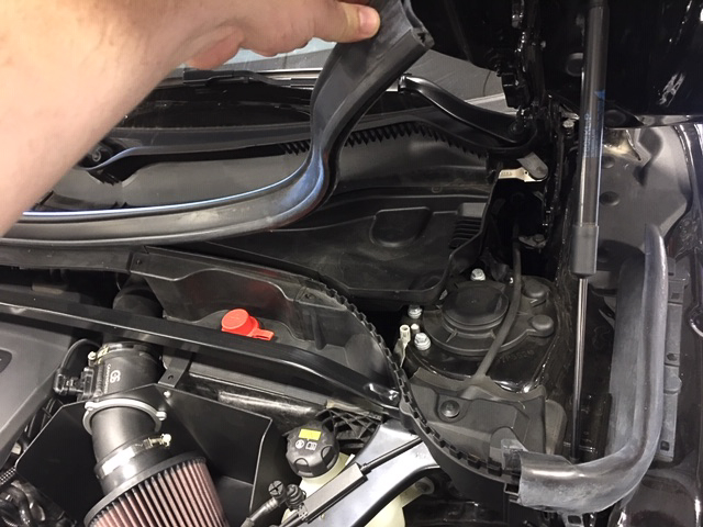
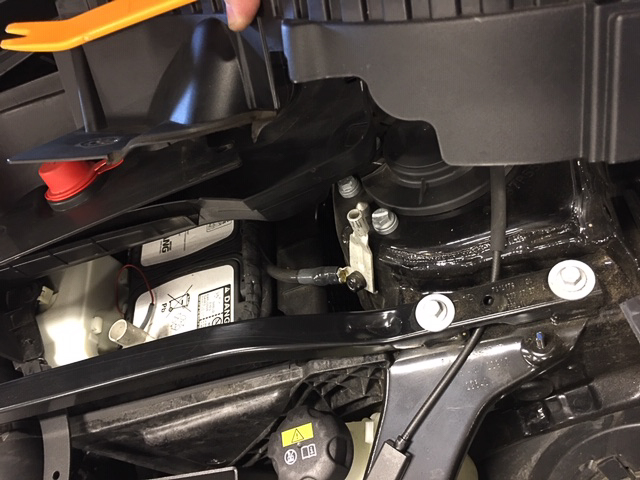
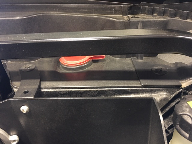
- First things first, we need to disconnect the negative battery cable to ensure we aren't working with any live circuits. To get to the battery, we've got to get some stuff out of the way. Start by pealing up the rubber seal that separates the rain drainage area from the rest of the engine compartment.
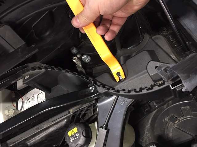
- Once the seal is removed we can also remove the "s" shaped plastic piece, this will help with wire routing down the line. Use the trim panel tool to pop the clip, and then the whole thing will come off.
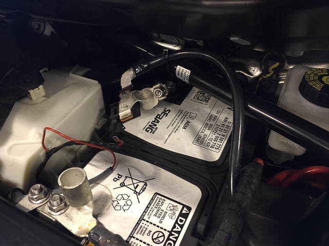
- Now we can access the battery box lid. It is secured by 2 8mm screws. Remove the lid and disconnect the negative battery terminal by loosening the 10mm bolt on the clamp. Once you've disconnected the cable, it's a good idea to secure it to the support bar to make sure it doesn't come into contact with the terminal while you're working.
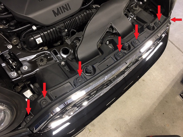
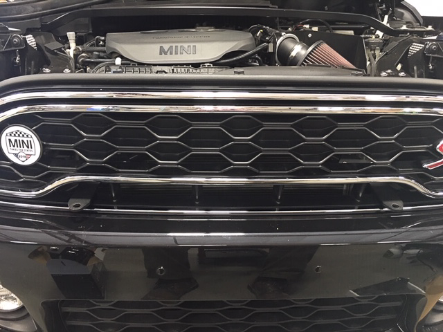
- We will need to remove the grill. Start by removing the 7 T30 Torx screws across the top of the grill.
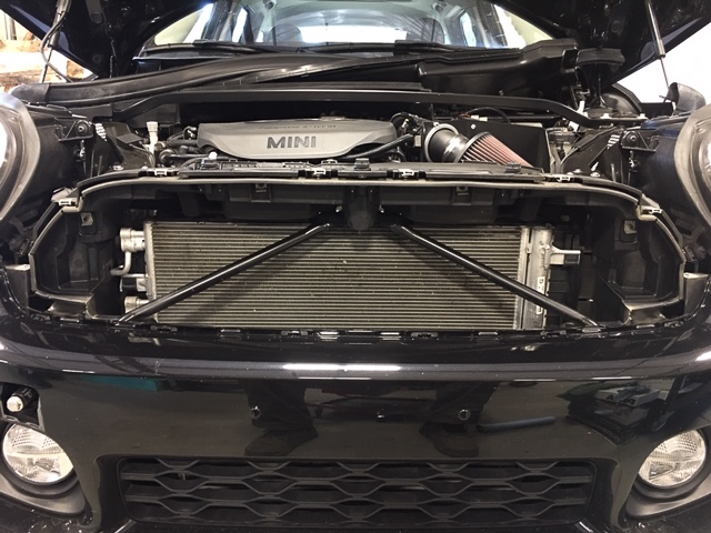
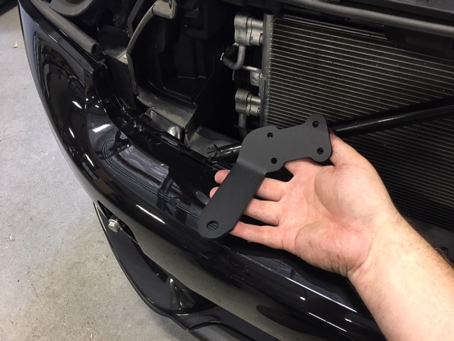
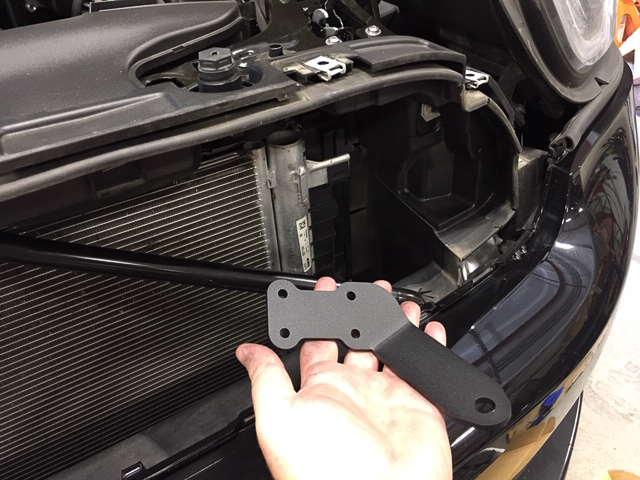
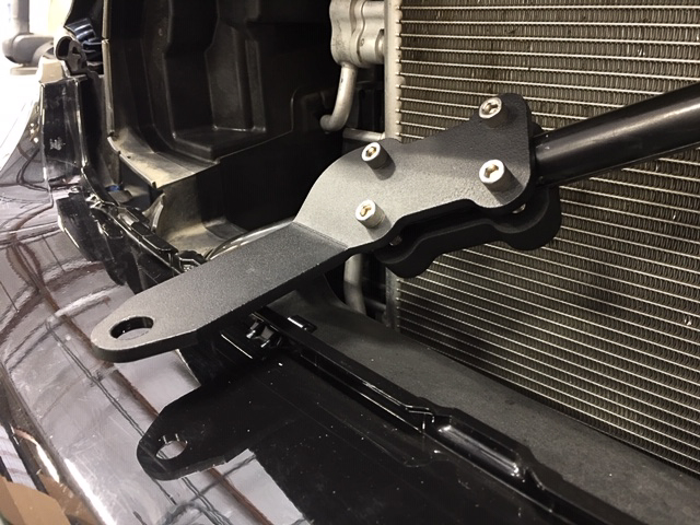
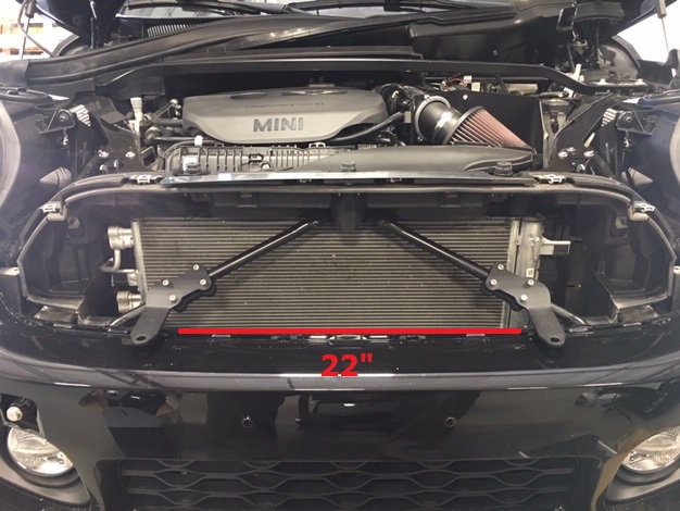
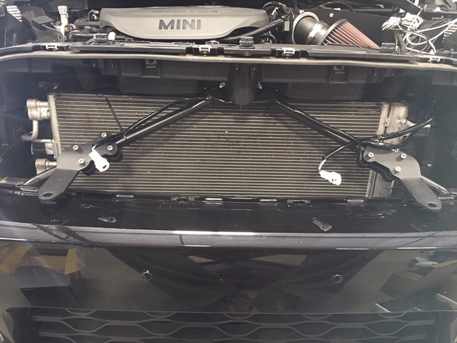
- With the screws out, gently pull the grill forward slightly to reveal several tabs that secure the bottom to the bumper. To disengage the clips, push down on the tab while wiggling the grill outward. Once the grill is out, you'll now see the v-brace that our brackets will attach to. There is a left side and right side bracket, so take note of the orientation and placement of the brackets below:
- Grab a bracket and insert one of the 1/4-20 x 1.25" cap screws through each of the four holes. Hold the bracket and dogbone in place on the cross bar, and finger tighten the screws into the dogbone.
- The positioning of the brackets is important, so take some time now to get the brackets mounted level, and centered on the car. The inside edges of the light tabs should be approx 22" apart. This should result in the tabs resting about an inch off of the top surface of the bumper and give the necessary spacing for the quad light bracket if you choose to install one at a later date.
- Once you've got the brackets positions set, take the grill and set it in place to ensure you've got the brackets positioned right. Once you're satisfied with the fitment, go through and evenly tighten the bolts with your 3/16" hex wrench. They don't need to be extremely tight because if you tighten them too much you'll risk crushing the bar.
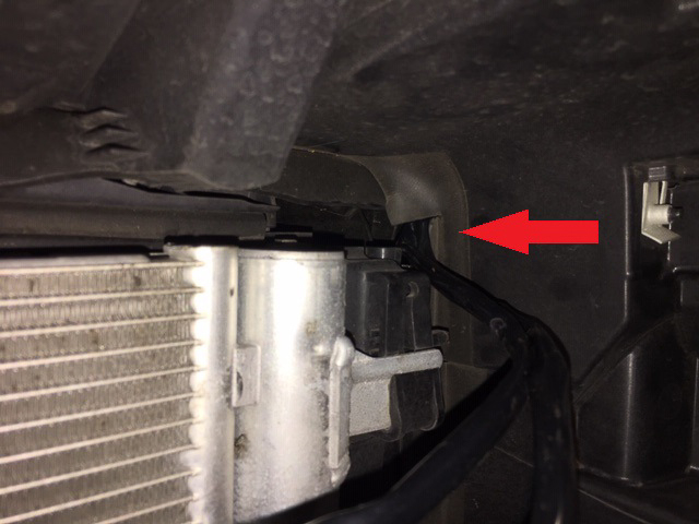
- Before we reinstall the grill we're going to take this opportunity to start running some wires. Break out the PIAA light wiring harness (or the wiring harness of your choice of lights) and straighten it out to get a good visual of the various components. Take the two light leads (one short, one long) and feed them through the opening in the top right corner of the space behind the grill.
- Send the longer of the two light leads over to the passenger side and zip tie the plug near the light bracket. Do the same with the driver side.
- With the light brackets mounted and PIAA light wiring leads installed, set the grill back into place. Use the palm of your hand a gently bump the grill along the bottom edge listening for the telltale sound of the tab clips clicking back into place. Now you can reinstall the 7 T30 Torx screws along the top and side of the grill.
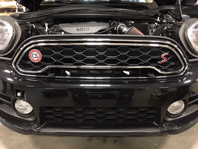
The next task is to get access to the mounting points for the bracket. Ultimately the brackets with protrude through the grill at the two points shown below:
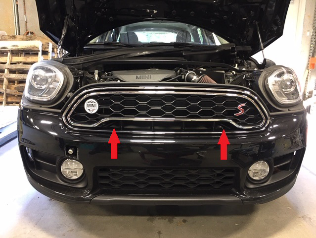
Install the Auxiliary Lights
- Open the PIAA 5” LP550 high intensity LED driving lamp kit and lay out the rest of its contents. You should have (2) driving lamps w/ their respective hardware, some remaining components of the wiring harness, and a set of installation instructions. Please read through the PIAA instructions in addition to what is presented here to have a broader scope of the process.
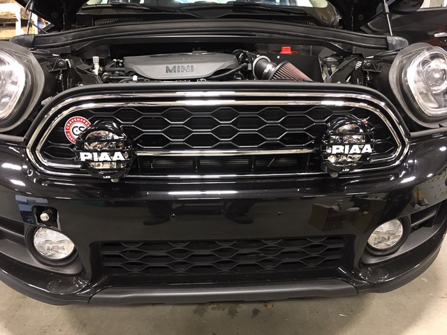
- Mount the PIAA lights to the CravenSpeed brackets utilizing your 19mm box wrench. We left off the rectangular rubber pads on the bottom of the PIAA light mounts to minimize any vibrations and make for a more solid attachment. Reach into the grill and grab the plugs on the end of the PIAA light harness and connect them to the plugs on the LED lights. Tuck the excess wiring into the grill and they should drop back down behind the bumper out of sight.
NOTE: Whether you have purchased our kit with the PIAA lighting or will be supplying lights of your own choosing, the following steps will be very similar as far as routing of the wiring and mounting of the various harness components.
Install the Wiring Harness
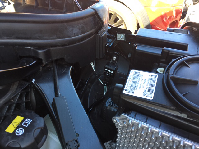
- With the light leads already installed, we’ll now need to locate a suitable location for the PIAA light harness relay. It needs to be mounted vertically so that water won’t be able to collect inside of it. Our F60 has an unused tab just behind the driver side headlight so we took advantage of this and mounted the PIAA relay to it with the included ¼”-20 button head screw and locknut. Coil up any excess wiring between the relay and the lights and ziptie them out of the way.
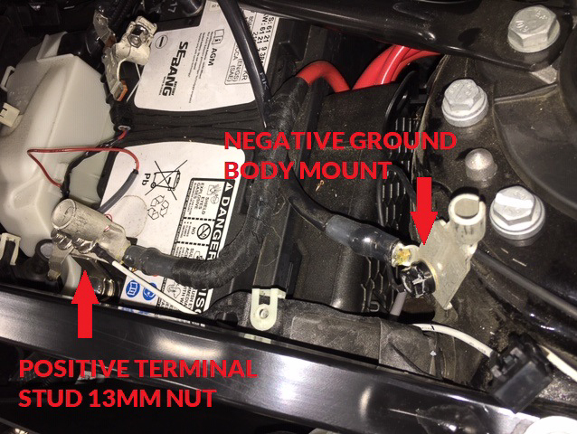
- There is an accessory attachment point on your positive (+) battery terminal clamp that we’ll connect the PIAA relay power lead to (white wire with inline fuse). Strategically snake the wire over and use your 13mm socket and ratchet to attach the ring terminal to it. Mount your relay ground (black wire with ring terminal) to the battery ground bolt attached to the body of the vehicle. It’s a 13mm nut here as well.
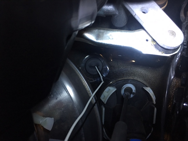
- Next, we’ll need to send the PIAA on/off switch through the firewall and into the interior of the MINI so you can activate the LED driving lights. If you peek back to the firewall behind the driver side hood hinge, you should see a wiring loom harness (big rubber plug) and a wee round plastic cap just above and to the left of it.
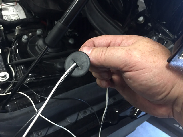
- If you can reach it from the inside of the engine compartment, go ahead and pull it out. The flanges of the cap are fairly difficult to get a good grip on, so you may have to go in through the back of the dash and push it out. NOTE: If you happen to drop this cap once it pops out, it can be extremely frustrating retrieving it out from behind the brake booster (ask me how I know). Have an assistant reach in from the engine side to grab it as you’re pushing it out from the inside. Once you’ve got it in your hand, use a razor knife and create a small slit across the face of the cap that the PIAA on/off switch wiring plug can fit through.
- Feed the PIAA on/off switch plug and related wiring through the firewall hole and replace the plastic cap. Pull the wires through to take up any slack and use a couple zip ties to keep them tidy.
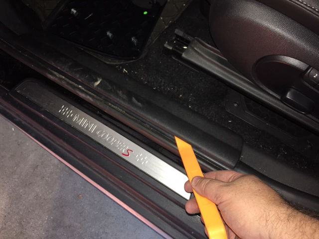
- How do you pull the wires though the cap, you say? Well, the easiest way is to remove some interior panels first. Here’s what you do. Begin by utilizing a trim panel removal tool and popping up the driver side door sill trim. It’s a pretty good bet that the grey clips underneath will remain in the body of the car and you’ll have to pull them out one at a time and reinstall them back onto the sill piece you just removed.
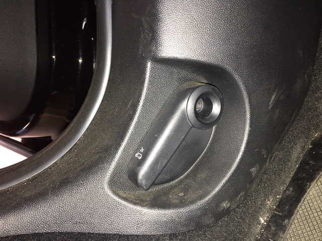
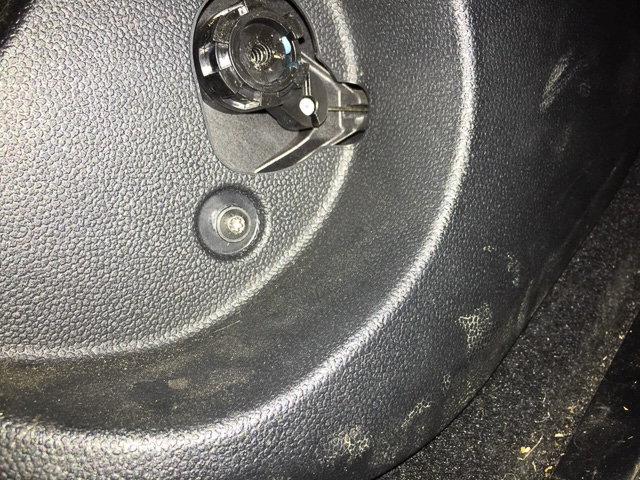
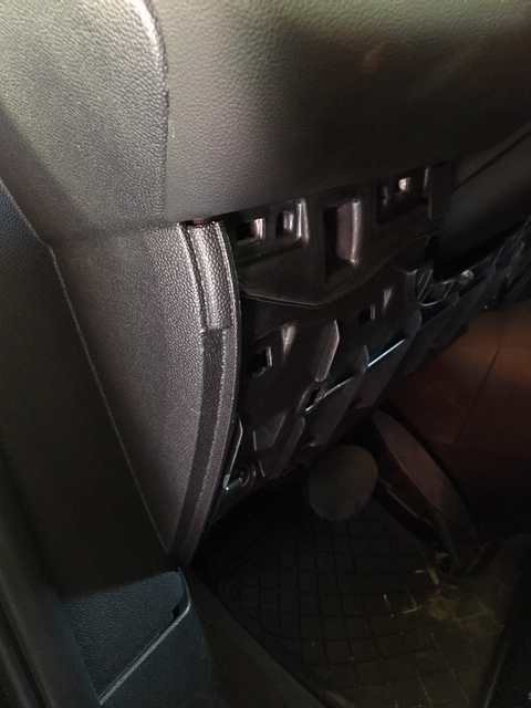
- Next, remove the driver side footwell kick panel (the one with the hood release). Utilize your T20 torx driver and remove the hood release lever. Once that is removed it will expose an additional T20 screw so remove that one too.
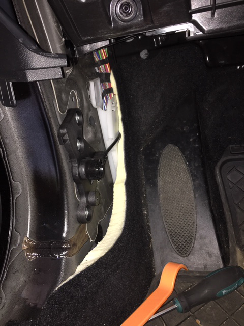
- Pull off some of the rubber seal along the sill that covers the kick panel and pop the panel off by pulling it toward the center of the car. Again, the clips inside may stay attached to the body, so pull them off and reinstall them onto the kick panel if necessary.
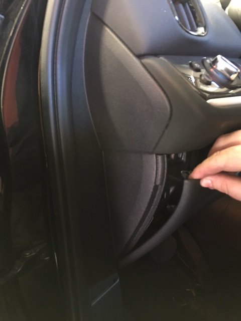
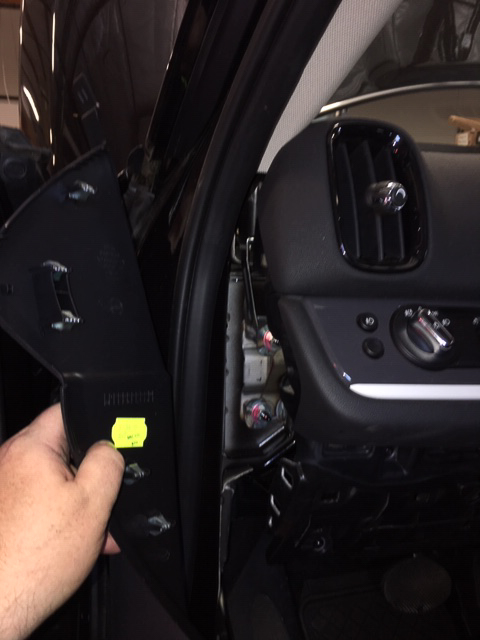
- Pop the lower steering column panel off by pulling it straight towards the seat.
- Pop the side dash panel off.
- You should now be able to look back behind the dash and see where the PIAA on/off plug is coming through the firewall plastic cap. Reach inside and pull enough of the wires through so that there is no slack inside the engine compartment.
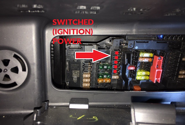
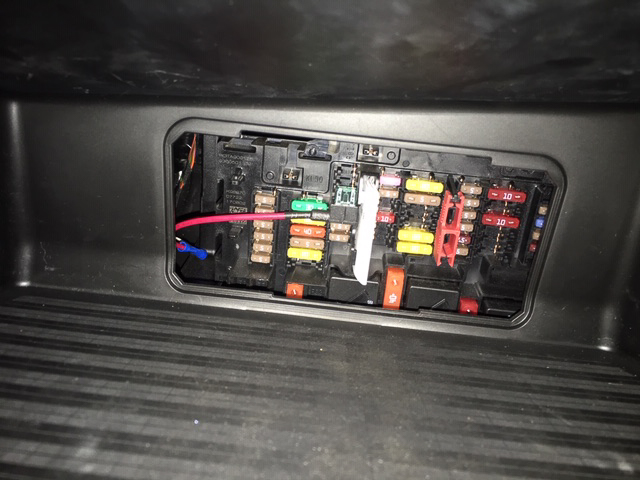
- Next up is finding a switched (ignition) power source from the MINI to power the PIAA relay. There is an extra white wire lead coming out of the PIAA on/off switch plug lead that will reach over to the fuse panel located above the passenger footwell and against the firewall. You’ll need to tap into a switched power source and we’ve included an ‘Add-a-Circuit’ with a 1mA mini fuse that should simplify this procedure.
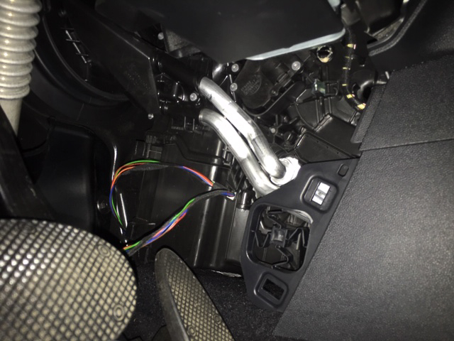
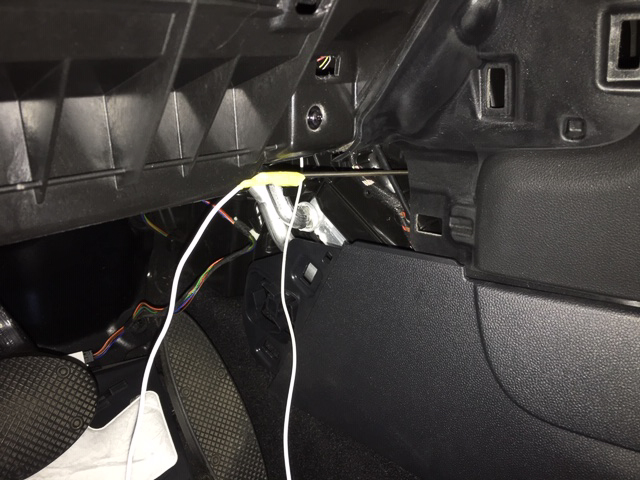
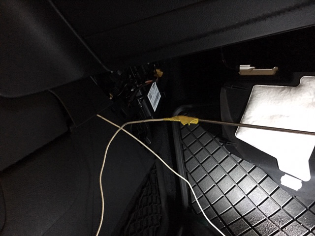
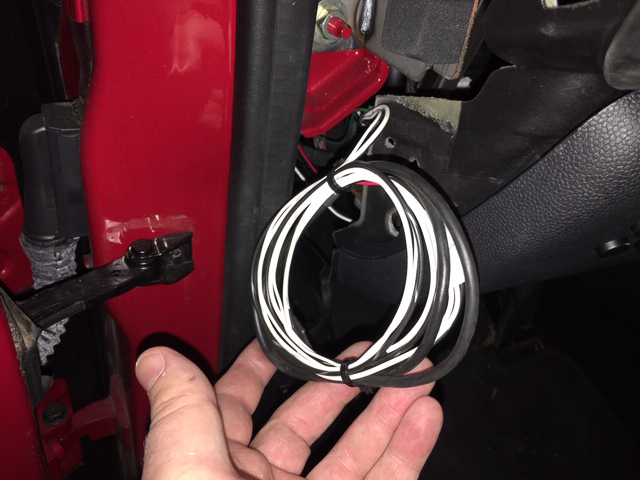
- Take the extra white wire lead coming off the PIAA on/off switch plug and feed the length of wire behind the dash and over to the interior fuse panel. The route we utilized was; under the steering column>(remove driver side kick panel)>down behind kick panel (avoid the heater core tubes)>through the center console>(remove pass side kick panel) up behind kick panel>over to the fuse panel behind the glove box. NOTE: A simple trick we used to send the wire through the center console was to take a length of rigid wire (coat hanger wire) and tape the PIAA switched power lead onto the end of it. Probe around with the wire and send it through. Head around to the passenger side and when you see the end of the wire, continue to pull it through.
- Located on the back wall of your glove box should be an access hatch to the interior fuse panel. Take a look at the image below and take note of the switched (ignition) power locations.
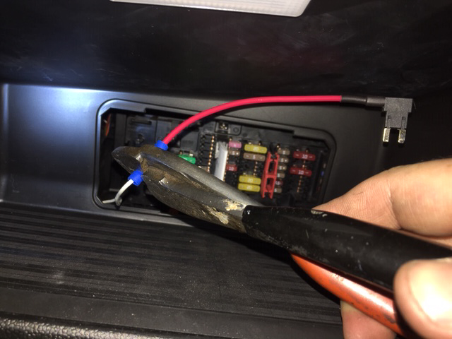
- Place the 1mA mini fuse into the top location on the ‘Add-a-Circuit’ and crimp the included length of wire to its tail. Install the ‘Add-a-Circuit’ into one of the designated switched power locations on the fuse panel.
- Once you have your switched (ignition) power wire sorted out, secure the wires under the dash with a couple zip ties and replace all your interior kick panels. Loop up the excess wires and plug in the PIAA on/off switch.
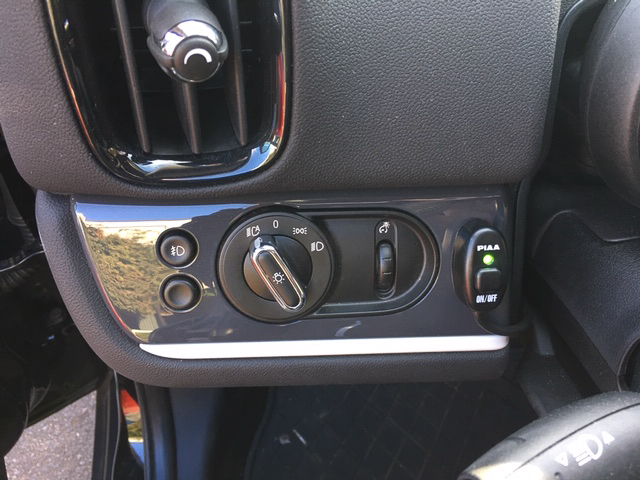
- Before installing the driver side panels, reconnect your MINIs battery to test the functionality of the lights. If everything checks out and your driving lights function normally, button everything back up and proceed to aiming your beam patterns as shown in the PIAA instruction manual. If they don’t light up on the first try, double check your connections and ensure that you have proper ground for the PIAA relay. Locate a suitable spot for the PIAA on/off switch and affix with the included double-sided tape.
PIAA lamps are intended for use solely as auxiliary lighting. Lighting laws vary from state to state. PIAA makes no representation or warranty, either expressed or implied, as to the legality of its products for street use on any vehicle or in any location. PIAA lamps are designed to improve visibility during night time motoring and inclement weather conditions. However, irresponsible use of any auxiliary light can be dangerous and illegal.
