
Durability Testing Our GR86 Short Shifter - Part 3
Posted by Logan on 6th Aug 2024
Welcome to part 3 of our deep dive blog series on how we tested our GR86 short shifter.
When we left off, we were wanting to continue testing of the shifter after a slight redesign and rebuild of the machine. Our goal was to make the machine more reliable, so that it required less attention and could put in some endurance runs without stopping. We needed to address two issues that were causing stoppages. Firstly, we wanted to eliminate any deflection of the air cylinder piston. Second, we wanted a more robust system to detect when the shifter had reached each end of the stroke.
The Sled
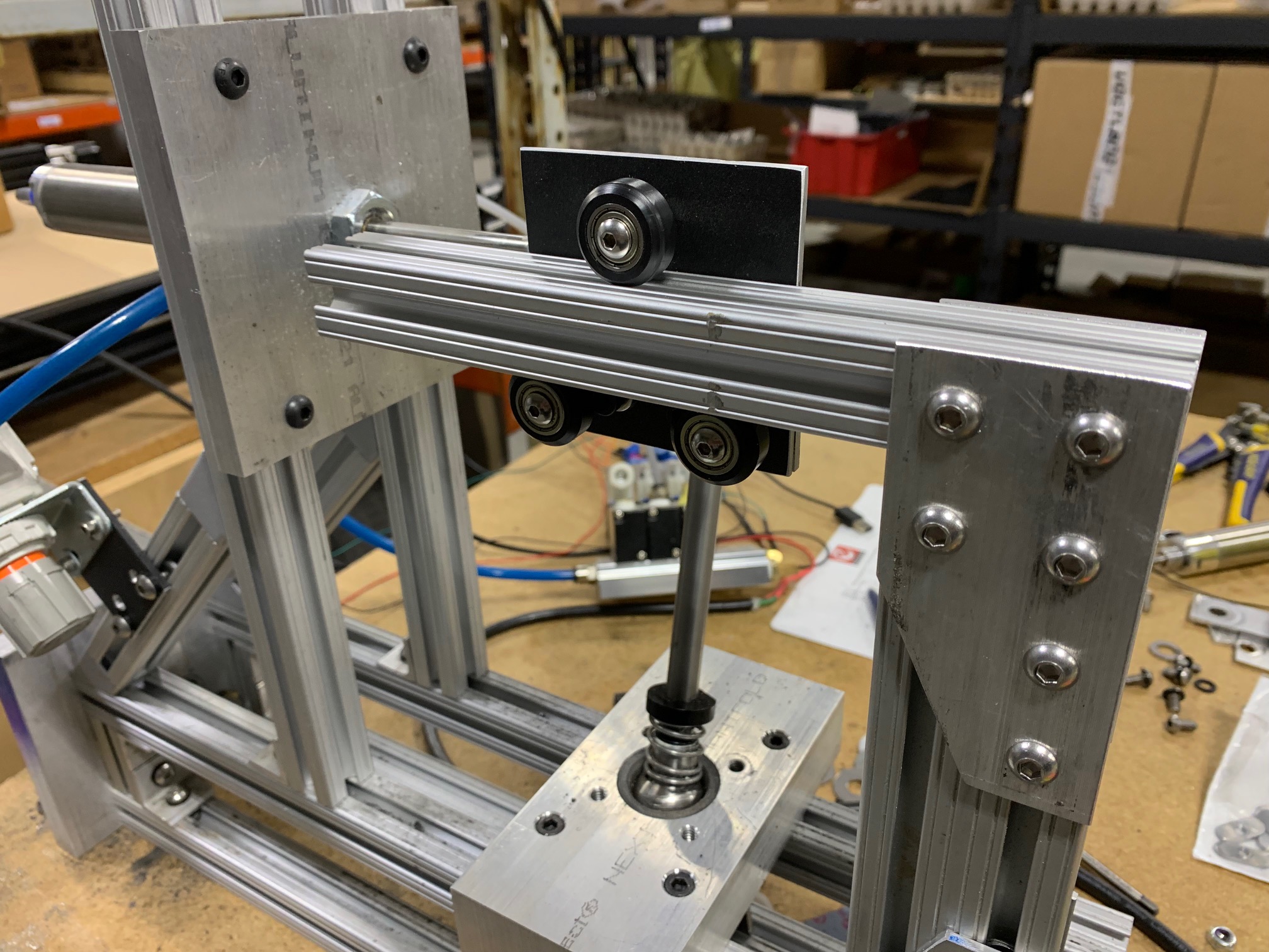
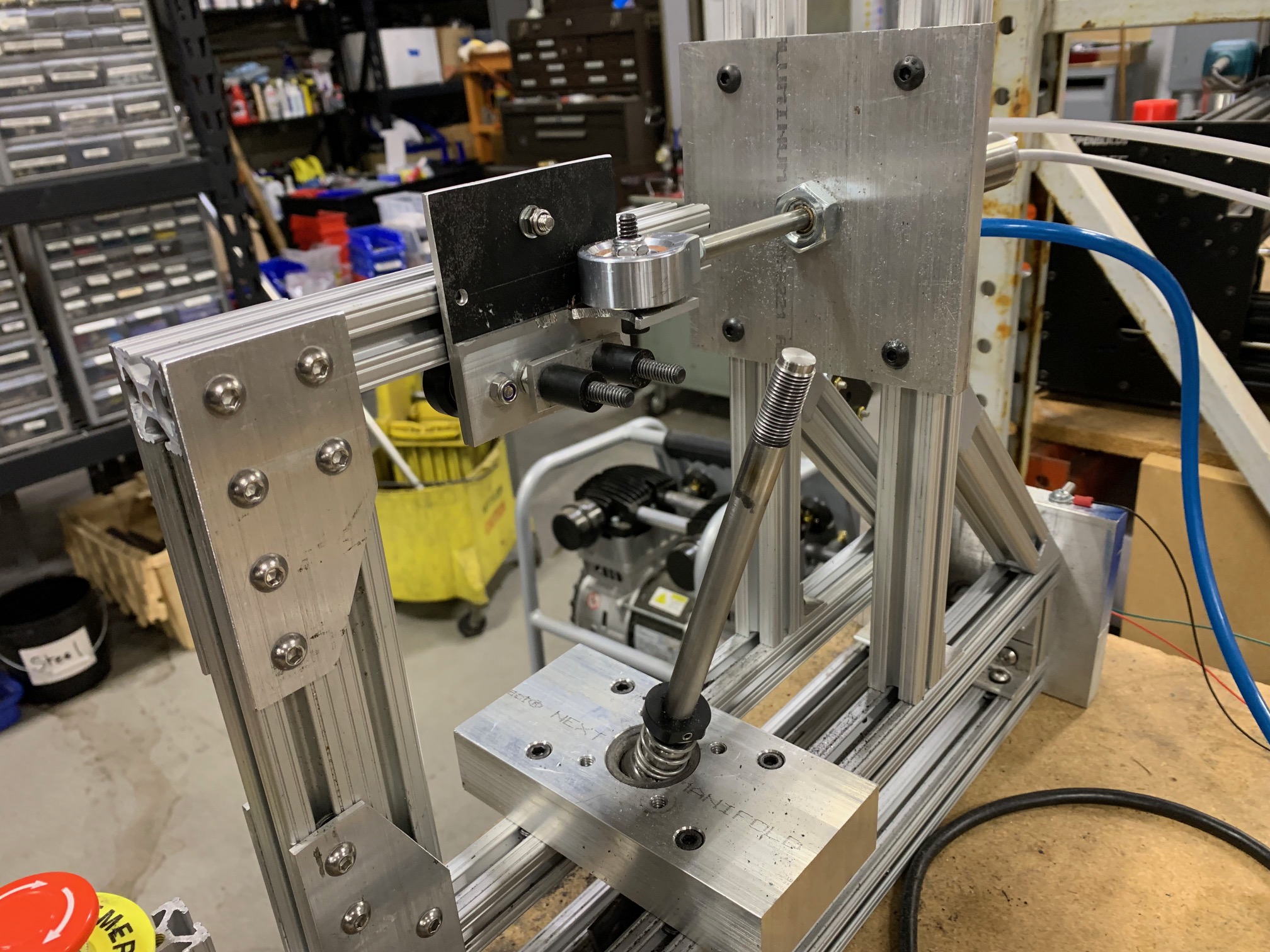
To resolve the issue with the air cylinder, Tristan came up with a design that would isolate the motion of the piston from the motion of the shifter. This accomplished two things. The resistance forces acting on the cylinder would be greatly reduced, and perhaps more importantly, the resistance forces would be in the same axis that the cylinder was applying its own force. Thus, there would be little to no deflection of the piston, and the life of the cylinder would be greatly extended.
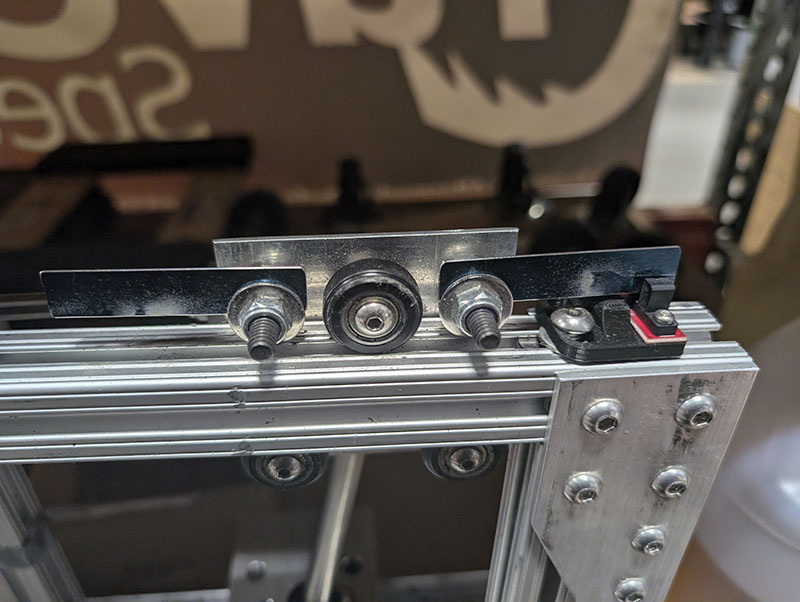
To accomplish this, instead of being attached directly to the shifter, the piston would be connected to a rolling sled which is held captive on a track by rubber wheels. The sled has a bracket that positions two pegs around the shifter shaft to push and pull it.
Giving The Machine Eyes
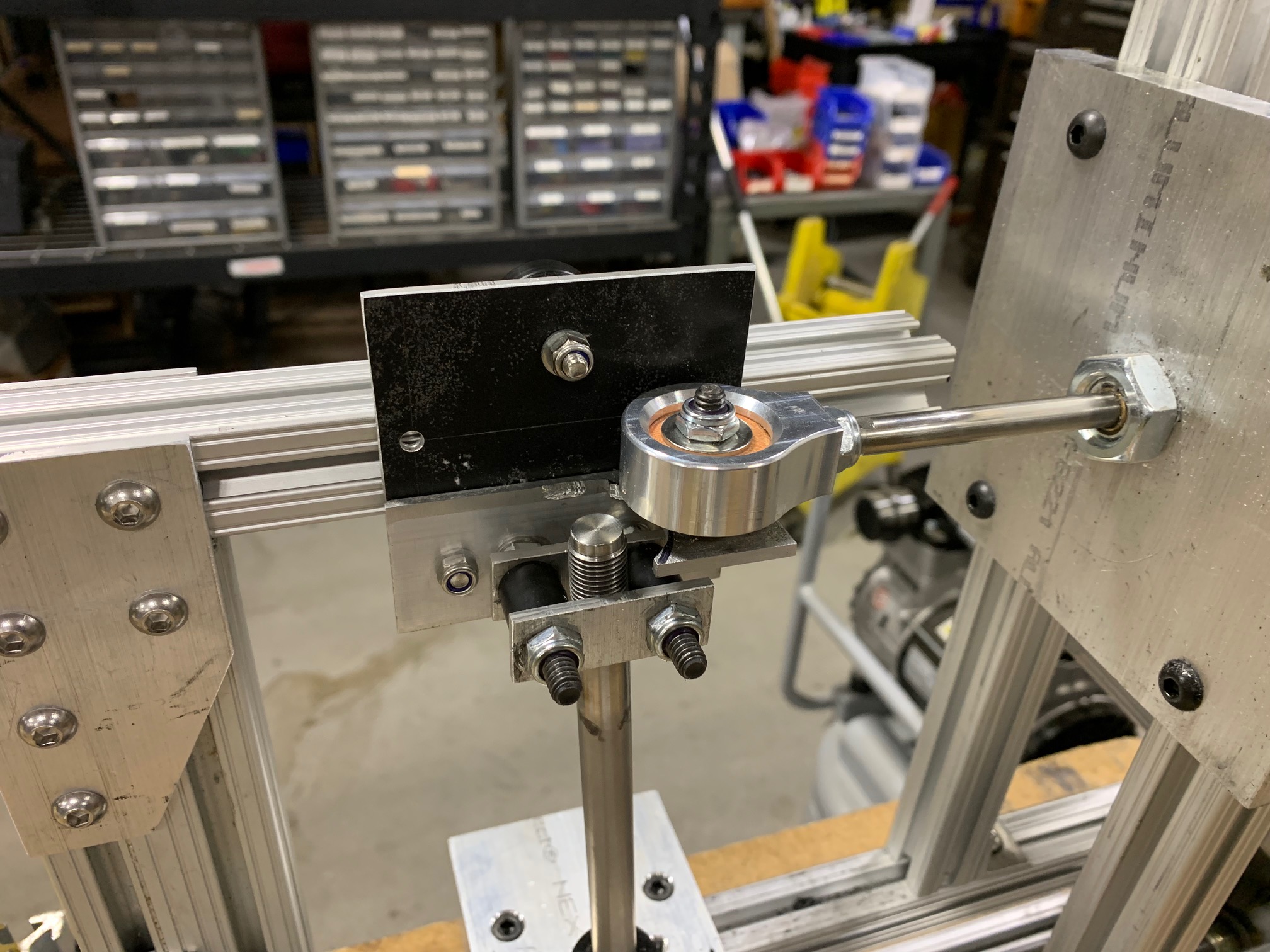
With the mechanics of the new mechanism sorted we just needed to come up with a better method to detect the position of it. The last version relied on conductive contact between the metal end stops on the shifter linkage and the frame of the machine. With the motion and buildup of the wear debris from the acetal bushing, conductive contact was often inconsistent. Since the machine was programmed to stop if it didn't detect that the shifter had reached the end stop, this meant we were constantly having to restart and clean the machine. We wanted to eliminate the possibility of this happening, so that the machine only stopped if there was actually something wrong. Our attempt at this was to use optical sensors. This would avoid the necessity of any parts needing to come into contact at each end of the shift stroke, and thus remove many possible points of failure. The design consisted of two metal "flags" on opposing ends of the sled. With an optical sensor attached to the frame on each side. At the end of each stroke, the flag on the sled would trigger the optical sensor and indicate that the shifter had indeed reached the end of the stroke.
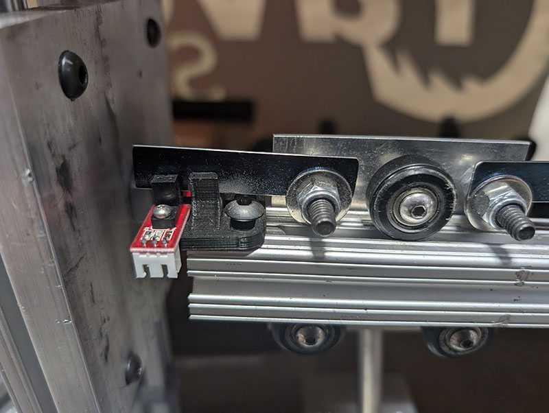
As you may be able to tell, this method has its own challenges. Keep in mind, with this project we are mostly trying to use materials we had on hand. With the sensors we had, the opening slot for the beam was quite small, this meant that there was some precision required to get the interrupter into the slot without damaging the sensor. Jacob designed mounts for the sensors that were adjustable and also featured guides that were meant to guide the interrupter into the correct position. As you can see these didn't always work.
In the video, I am simply operating the machine by hand, under operation the machine is moving at a more rapid pace. Over time we did have issues with the interruption flags being as precise as we needed and broke a few of the sensor mounts.
Reaching Our Goal
With the machine redesigned, rebuilt, and a new shifter installed, it was time to push on for some more long term testing. We wanted to run it at 25 psi, which would equate to a very heavy handed shift at 15 lbs of force. It took some time to get the new setup dialed in. While, ultimately, it was more consistent than the previous version it wasn't to the point where extreme long term testing was feasible just yet. We ran the machine again for over 1.2 million shifts, but were still having some consistency issues, particularly with what we believe to be electrical interference, which we weren't sure were worth solving. We had a team meeting and decided to look at what the shifter had already accomplished, and see if we really felt that further testing was necessary. When we looked back at the testing we had already done, we were all kind of surprised! So far the shifter had withstood:
1st Shifter
- 1 million shifts at 25 psi (~15 lbs) zero failure
- 1 million shifts at 60 psi (~60 lbs) lower pivot loose, shifter intact
- 500,000 shifts at 85 psi (~75 lbs) lower pivot loose, shifter intact
2nd Shifter
- 1.2 million shifts at 25 psi (~15 lbs) zero failure
Writing all of that down on one list kind of put into perspective how strong the shifter really is. It became clear that doing 1.5 million shifts at absolutely ludicrous shifting force and remaining intact with only one piece coming slightly loose was beyond what any of our expectations were. Even at a force that in the real world is near the maximum of what would be seen, we did 1 million shifts with two different shifters and had zero issues whatsoever. We've always stood behind our products, and have always gone above and beyond to correct our mistakes when they do happen. With our GR86 shifter, we can safely say that it is something we are proud of and extremely confident in!
You can find the GR86 Short Shifter here Or shop all GR86 products here